bender

Signal diagrams in every stage

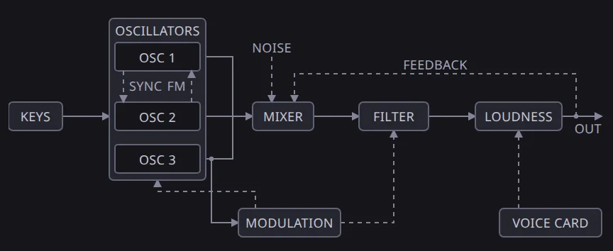
The Growler voice card diagram. Keys feed three oscillators, then the mixer, filter and loudness, with noise, feedback and modulation wired around them.

Press a box in a stage’s diagram and its knobs open under the drawing.

The Growler voice card. Sync and FM wires join the oscillators, and noise and feedback enter at the mixer.

A box lights when a knob inside it is off stock. These drums have been rolled, and PADS is the open box.
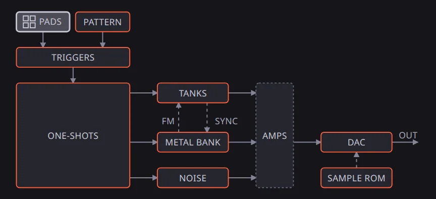
The toy drums. Pads and pattern feed the triggers, which feed the one-shots, tanks, metal bank and noise, then the amps and the DAC.

The FM chip’s diagram shows its operators as a close-up under the chip’s box.
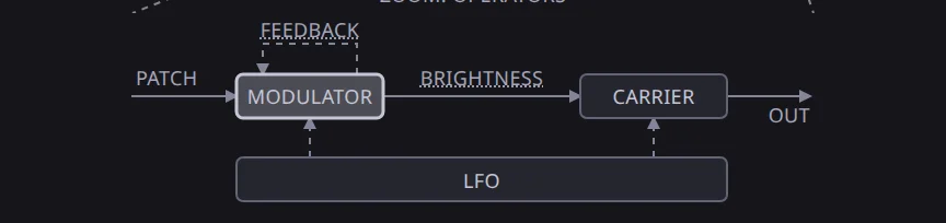
The FM chip’s operators. The modulator has feedback, and the carrier and LFO sit beside it.

Each bus is a ribbon with a trace per bit. Press a trace to fault it.
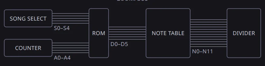
The toy keyboard’s buses. Song select and counter into the ROM, the ROM into the note table, the note table into the divider.

The tape machine’s wires light once its mix is up.
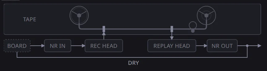
The tape machine. The board and dry wire, noise reduction in, record head, tape loop, replay head, noise reduction out.